Friday, January 25, 2013

DHT11 temperature sensors

=== This log post is in raw form. This is not the final presentation, but making information available is more important than making it pretty. ===

Today I received 4 DHT11 temperature sensors. They were a deal, but it turns out they're all labeled in Chinese.


Google searches bring us to the Adafruit page for the device. Under the downloads tab, you'll find the manual in Chinese. Fortunately, Google Translate gives us something passable. Even better, there's a similar guide in English linked from Adafruit.


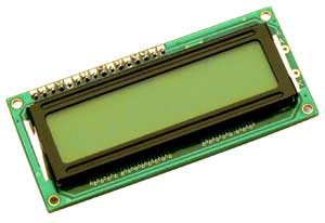
The guide lists various specifications for accuracy and operational speed. It mentions a 1 second delay several times. Near the bottom is the pinout. While the device has 4 pins, only 3 of them are used; one is merely there to physically connect the device to the mounting board. This is good because those pins are thin and flimsy. I bent one putting it into the solderless board.

Pin Name
Note
1
VDD
Powered 3-5.5VDC
2
DATA
Serial data, single-bus
3
NC
Empty feet vacant
4
GND
Ground, power supply negative

But this is backwards, if you look at the label. From the above image, the VDD goes on the rightmost pin, GND on the left, with the DATA next to the VDD. The code sample that worked for me specifies the DATA pin should connect to the Android's analog A0 pin.

Elsewhere the guide mentions a single-pin bus, so I'm assuming it works much the same as the Ping ultrasonic distance sensor, using the same pin as input and output.

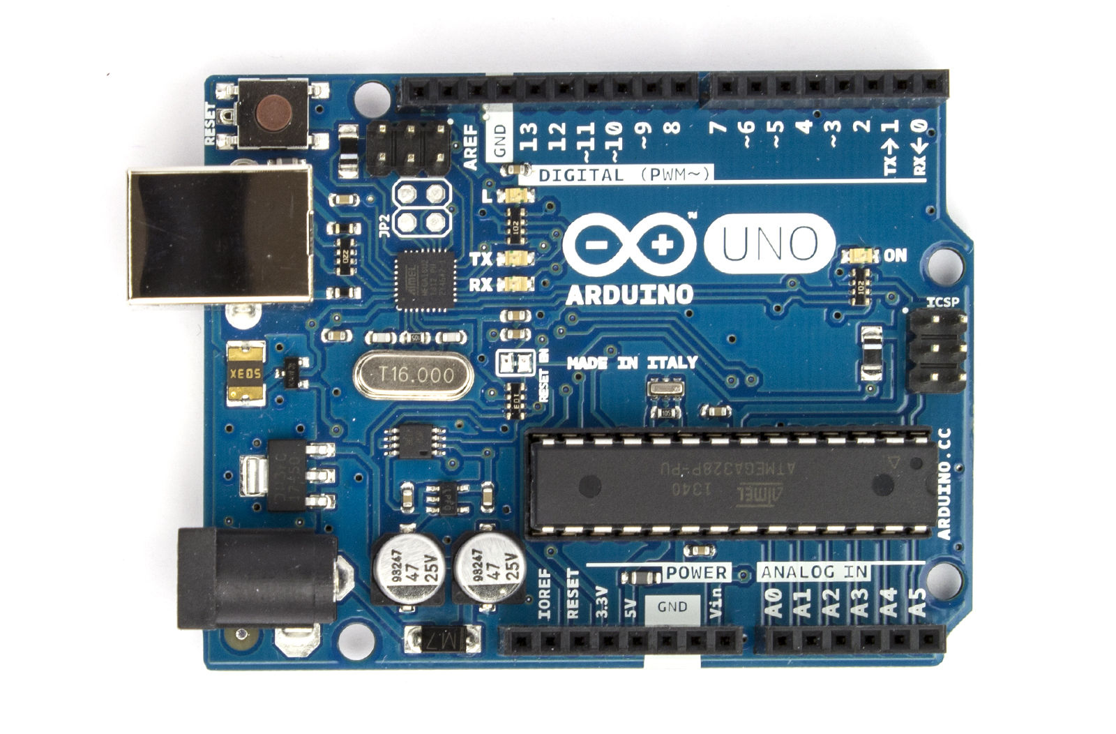
So how to get it working on the Arduino? 

First, you need to make a DHT11 library. You'll need to make a new folder in your /arduino/libraries/ folder. Then you'll need to fill it with dht11.h and dht11.cpp, which tells the Arduno's C++ compiler how to handle the commands for the DHT11. I got the files from the bottom of this page -- you actually make a text file, rename it, then copy the code from the page, and paste it in the renamed text file. (You might be able to click "get code" at the bottom of each section, but all that did for me was display the code in my browser).

Once you've got the libraries in place and have restarted the Arduino IDE, you should be ready for code. While the code for the libraries seems to work great, the example code on the same page provided a repeating pattern of letters and numbers and weird shapes. Through some digging, I was able to find another source. The first section of code on this page, however, provided a nice, repeating output:


Current humdity = 38.0%  temperature = 21.0C


So I think we have a keeper. I'm planning on combining this with the xbee wifi device, to make a networked wireless device you put in your fridge. I want it to host a webpage, showing temperature statistics for your refrigerator. I know it's not a moving robot, but robots are about automation. Maybe I can kickstarter this!


Xbee

=== This log post is in raw form. This is not the final presentation, but making information available is more important than making it pretty. ===

Today in the mail I got a couple Xbee wifi modules. They fit on the Wireless SD shield, among others. When I was buying them, I thought Xbees would just connect to wifi hotspots, or at least enable an Arduino to do so. This isn't exactly the case. As I described in the Wireless temp sensor post, they use the same frequency range as wifi, they actually use slightly different frequencies and channels. This does mean that the modules communicate with each other right away out of the box -- that is, they just work. And they can be programmed to be more selective about which Xbee antennas they connect with, based on an addressing system. Check out the Wireless Shield page fore more info.

Physical pixel is a Communications Example, and while I didn't get the pixel image going, I was able to have the LED activate when pressing H and deactivate when pressing L in the X-CTU terminal. 

Wifi

One of my big goals in working with these devices is being able to control wifi capabilities. I don't just want to have devices scan for networks and host webpages on them, I want them to be able to pinpoint wifi devices and travel to the device -- which would sometimes be a device held by a human, and sometimes be a charging station, device needing service, or some other target. I don't know how much of that can be done by an Arduino -- the ATMega processor isn't that beefy, so I might need to move up to an ARM, which means moving into Linux and much more developed networking stacks. It would be a solved problem from that perspective, and the weight and power differences aren't too big...

Like with the DHT11 temperature sensor, we'll need to add a couple of libraries to the Arduino IDE: XbeeWifi.cpp and XbeeWifi.h. Both can be found on this page, along with some examples for how to use it in code. You'll have to goto your Arduino/Libraries folder and make the /XbeeWifi folder, then copy the text for those files and save them in the /XbeeWifi folder.

Restart Arduino, and the libraries should be good to go. 

I'm still working on this part of the project. Check back later for more info!

Wednesday, January 9, 2013

OpenCV

OpenCV, or Open Computer Vision, is an open-source project to open up computer vision to the masses. Computer Vision is a process where a computer receives images from a camera somewhere, interprets these as an array or matrix, and does some math to analyze them. Sometimes the math is simple, like "find the orange circle, and the green circle, then line them up." Sometimes it's more difficult

Suddenly I realize we can make red and green circles on the walls with LEDs. Can we make "different colors" of infrared light with LEDs? Is anyone making infrared CCDs yet?


Sainsmart LCD2004

This winter, a gift I received was the Sainsmart LCD2004, which is a 4-row, 20-letter wide display, also known as a 20x4.


I'm happy to have received it, as I just bricked a 16x2 (2 rows, 16 letters wide) in early December. Interestingly, both use the same controller, Hitachi HD44780, to store and push the actual outputs to the screen. 


My LCD2004 has the PCF8574AT controller made by NXP, an 8-bit I/O converter for the 2-wire I2C bus. The PCF8574AT listens to the Arduino quickly on 2 lines, then spreads that info across 6 lines for the HD44780. This means the display will only take 2 pins instead of 6, and these aren't even commonly-used pins -- all 13 of the pins I like to use are still available. A dial potentiometer, to dim the display, is built in. A data sheet is available.


With the 16x2, I had to control all of the signals manually. This took up 6 of the Arduino's 13 pins, and a significant amount of code. But there's no reason to have to do this by hand when we have libraries and microcontrollers to handle it for us. How do microcontrollers talk to each other? Phillips developed a protocol, a common way of signalling, called Integrated Internal Communication or I2C.

Getting new devices means learning how to configure them, which is a big sticking point for this model of display. This blog post says to use the Arduino's A4 and A5 ports for SDA and SCL instead of the board's SDA and SCL ports, which are next to AREF and GND. The Arduino website confirms this: Uno, Ethernet [use] A4 (SDA), A5 (SCL). This forum post discusses which address to use in the code. Several of the recommended addresses, such as 0x27, 0x20, and 0x30 aren't working.


SCL is the Clock line, and SDA is the Data line. The Atmel ATMega chip doing the processing inside an Arduino runs at 16 megahertz, which is another way of saying it has a clock circuit sending 6 billion on/off signals per second. Hertz is an old-fashioned way of saying "cycles per second", and Mega relates to billions of something. So the SCL could be 16 MHz, but will probably be a much slower 100 million times per second (100 kHz or 0.1 MHz). 

Whenever the Clock line pulses, the value (1 or 0) on the Data line is written into that spot in memory --which is to say the magnetic charge (HIGH or LOW) for the patch of copper which creates that spot of memory is changed to match the Data line's magnetic charge. This happens once per clock cycle. The location written to usually changes on the clock cycle, and in this way information can be transposed from a series of inputs across 1 wire into multiple parallel inputs with their own wires.

None of which tells me which address to use. The author of the new LCD library says The base address for the PCF8574 is 0x20 and the base address for the PCF8574A is 0x38. Unfortunately, the base address my PCF8574AT isn't specified. I suppose I'll have to try every address, or grab a multimeter and test every pinout at every address, like I have that kind of time. But seriously, I'm not even sure the defined pinouts are correct.

Next steps:
A very thorough primer on I2C.
I2C Sniffer.
Sample code which is supposed to work, but doesn't.