Monday, April 29, 2013

MSP TryFi Prep

Today, I'm going to begin merging 2 disparate devices. We're going to start "pre-marriage counseling" for a union between 2 devices which can talk to each other, but aren't really intended to.

Bride and Groom


Our goal is to get the MSP-430 and the Xbee Wi-Fi radio to communicate. If we can have it report available networks over a serial connection, then it can host a webpage over wifi. To make this happen, we'll need to do several things:


1. Install CJBearman's XbeeWifi library into Energia
2. Make an SPI connection from the MSP to the Xbee -- 4 pins plus VCC (power) and ground
3. Make another connection for XbeeWifi library's 4 required pins
4. Transfer and run code


Sunday, April 28, 2013

Sunday Update

New Look!

I like orange!

New Inspiration

After re-reading CJBearmans documentation, I better understand the challenges with this project. I'm on the right track, as the library needs 3 more digital pins to better control the Xbee. (I wound up using Arduino Pin 5 for RESET, Pin 6 for ATN, and Pin 8 for DOUT.) Since the Xbee's designed to run at 3.3v and my Arduino Uno uses 5v, I believe I may have fried this Xbee radio.

Some drunken fool (possibly myself) scribbled out an idea on my whiteboard last night. I was eventually going to see if a TI MSP430 could handle both hosting a webpage and running an Xbee, but only after I got it all working on the Arduino. The MSP430 is a much smaller, cheaper development kit than the Arduino Uno, and its 3.3v processors run much slower -- 12MHz (or even 1Mhz) vs the 80Mhz processor in the Uno. But the processors cost about 1/10th as much as the Atmel processors inside the Arduino Uno, which is important for production. And someone has created Energia, an open-source copycat of the open-source Arduino compiler -- meaning we can literally run the same code on both processors. This means I can take all of the code with which I've been working on the Arduino and simply keep working in Energia (after importing CJBearmans XbeeWifi library into the other program)

So tomorrow I'll again be "Frankensteining" together 2 devices that aren't designed to work together. Isn't development fun?!?

Kickstarter

One main goal of this project has been to crowdfund with Kickstarter to start a (small or large) company.  I will have more information about this part of the project later this week.

GilgaTech

I've always planned for this page to be a workshop notebook, mainly focused on this company I'm learning to build. I've decided to launch Gilgamech's Technologies for my more general-purpose technology thoughts and pursuits.

Wednesday, April 24, 2013

TryFi 4

TryFi 4 - The SPI Try

I've been trying to line up which pins to provide the XbeeWifi library, so it can communicate with the Xbee wifi radio. Once I have this completed, it should be somewhat easier to make it host a webpage over the wifi connection.

Let's go over what I have learned so far:
*SPI uses 5 pins to communicate:
  -MOSI = Master device (Output) to the Subordinate device (Input)

  -MISO = Master device (Input) from the Subordinate device (Output). Named after a tasty soup, this is opposite of MOSI.
  -CLK = Clock. It's a circuit in a processor that's like a camshaft in an engine, in that it synchronizes all of the other parts. One master device can provide the clock signal to multiple subordinate devices.
  -ATN =Attention This allows a subordinate device to tell the master device that it has information to send. 
  -SEL = Select. This pin is used by the master device to tell a subordinate device to transmit data. This allows designs where MOSI, MISO, and CLK are shared between several subordinate devices, and each subordinate will only use the MOSI and MISO lines (also known as a Bus) when their SEL is turned on during the CLK pulse. This would save pins, allowing more subordinates per master. 

*CJBearman's XbeeWifi library calls for 3 of these plus 1 additional pin:
  -RESET - Reset. This is optional, but allows for the Xbee to be reset into SPI mode by the library. The other option is to manually configure the Xbee with X-CTU.

*The Xbee uses the following pinouts:

  -MOSI = 11

  -MISO = 4

  -CLK = 18

  -ATN = 13

  -SEL = 17
  -RESET = 5

*Arduino Uno SPI pinouts:
  -MOSI = 11 & ICSP 4

  -MISO = 12 & ICSP 1

  -CLK = SCK = 13 & ICSP 3

  -ATN = 

  -SEL = 10 (SS)
  -RESET = 1 & ICSP 5

Something to note here is the Arduino Uno's ICSP header has these same pins -- it seems pin 11 and ICSP 4 both connect to the same pin on the Atmel ATMega328. A good post with some very technical details helps me to sort this out. I'm not completely sure that Reset on the Uno is the same Reset as the Xbee is looking for. 

So far, we have:
Select: 10
Atn: ? 
Reset: 1?
DOUT: 12

For the library to work, we have to have at least the first 2 filled in. Out of desperation, I'm manually wiring the Reset and ATN pins to 5 and 6

Here the yellow wire runs from Arduino
Pin 5 to Xbee pin 5, while the white wire
runs from Arduino Pin 6 to Xbee Pin 17 

Looking at the pinouts...

Monday, April 22, 2013

TryFi 3

In the past post, I did the easy work of getting the XbeeWifi code running on the Arduino. This time, I'm looking at pinouts to connect the Xbee into a Wifi program. This is the last major puzzle piece I haven't yet had.

Tryfi 3 - Try and try again

More specifically, I'm trying to fill in these 4 variables with the numbers of the correct pins:  

  bool result = xbee.init(XBEE_SELECT, XBEE_ATN, XBEE_RESET, XBEE_DOUT);

Higher in the code, we see the actual pinout values in use:

  #define XBEE_RESET 20

  #define XBEE_ATN 2
  #define XBEE_SELECT SS
  #define XBEE_DOUT 23

After re-reading the Xbee Spec and the Introduction to SPI on Xbee, I have some slightly clearer understanding of SPI as a hardware protocol, a way for 2 processors to communicate. Basically, we're setting the right pins so the Xbee's processor and the Arduino's processor can hear each other. 

From the Xbee Spec, we can see the pins on the Xbee that we're looking for -- Reset = 5, ATN looks like ATTN = 13 (ignore the n), and Select could be SSEL = 17. DOUT looks like 2, but I'll come back to that later.

Well, I'm getting lots of info on what pins the Xbee uses, and lots of this SPI stuff is supposed to be universal -- basically a small but fairly complex universal language which all processors can speak. It's like UART, (universal asynchronous receive & transmit) which is basically a much simpler language that all processors can speak. There are lots of these "universal" languages, but SPI is the one we're interested in.

Here is one of the diagrams from 
the Xbee Spec. Note the highlight.

Something to note is 2 different naming methods for the connections -- DIN & DOUT vs MOSI & MISO. 'Master Out Slave In' matching to 'Data In' -- since the Xbee will be 'slaved' to the Arduino's clock frequency, the way ancient sea slaves rowed to the drummer's beat. 'Master In Slave Out' connections are also named the Data Out connections from the Xbee. So one of the 4 variables we're looking to fill is the Xbee DOUT, which is also the SPI MISO connection (which is actually pin 4 on the Xbee, not pin 2 -- pin 2 is the UART DOUT).

Maybe I'm looking at this the wrong way -- I have lots of info about how Xbee uses SPI, but what I need to is the pins the *Arduino* uses. Well, Google directs us to a gold mine! Aha! Looking down the page, we finally get our answers:


So this gives us 1 of the variables, and confirms another -- We know that Xbee DOUT should change from 23 to 12, and we know Xbee Select is correct in being set to SS, as SS is a variable for 10. Now, we just need the Xbee Atn and Xbee Reset pins.


Friday, April 19, 2013

TryFi 2

TryFi 2 - The Second Try


This morning, I'm hacking on the XbeeWifi again.
I'm still looking for a good solution to prevent static 
shock. The Arduino retail box works pretty well.

Looking over cjbearman's github page, the technical details are fierce, but luckily examples are included. After loading several up, I'm starting to see common patterns in the code. There's a couple extra subroutines (modules? functions? O_o) to handle different wifi scanning features. Unlike the Ethernet shield and library, we'll have to manually scan and handle data coming in and out. This could get messy.

Well, let's give it a try. Network Scan sounds like a good example -- it should output a list of available wifi networks, which is almost always an essential feature.

XBee Init Failed? Loop forever - game over, man!

What happened here? Well, the Arduino sent signals over to the Xbee, but the Xbee didn't respond. Why not? Well, this is the (boolean: 1 or 0) result of  a process on the Arduino, sent across 4 pins from Arduino to Xbee. Looking at the code, we see this in the line:

   bool result = xbee.init(XBEE_SELECT, XBEE_ATN, XBEE_RESET, XBEE_DOUT);

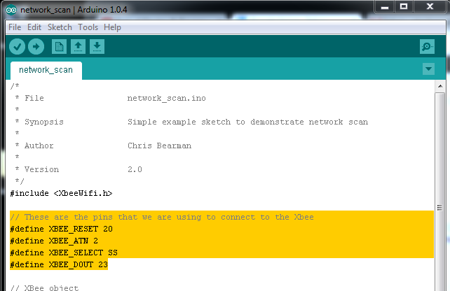
What does this mean,, when translated from C to English? We're going to set Result to either 1 or 0, based on what xbee.init says about the 4 variables between the parentheses. If you want to be a programmer, please don't use all caps for your variable names. So where are these variables declared? At the top of the code: 

"You're supposed to change these variables to
match your board's connections, you noob!"

Yea, so I forgot to change my pinouts. I'm not even sure which Arduino Uno pins connect to the Xbee. So the Arduino is expecting to use pin 20 for the Xbee Reset feature, and 23 for DOUT....so let's change that. 

Xbee Pinouts

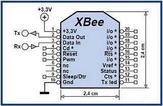
So where do we find the correct variables? First, let's start with the Xbee pinout:

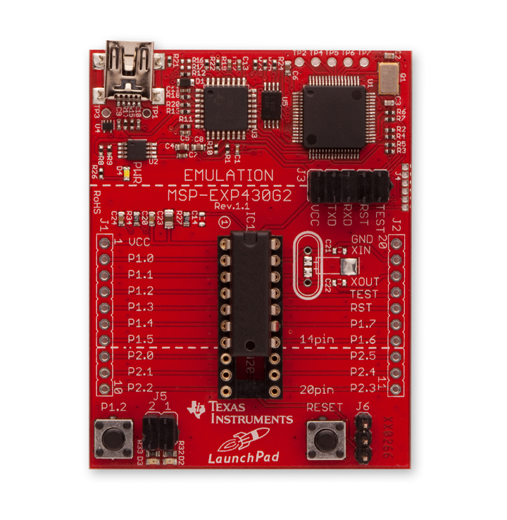
This is the same 20-pin Xbee shield which can be seen
in this post's first image -- it's plugged into the Wireless
SD Shield.

We need 4 variables from the Xbee - Select, Atn, Reset, and the D-out. Right away we see pin 5 is Reset and pin 2 is Data Out, now we'll need to see how those get routed through the Wireless SD Shield and into the Arduino. Select and Atn aren't obvious from this, but maybe they'll pop up in the specifications. 

SPI


Looking at the scary schematic, the Arduino Wireless SD Shield page, and cjbearman's github, it's really not obvious which pin is actually used for which output. But his github does describe this library using SPI to communicate. Wireless SD Shield takes up pins 11, 12, & 13 for SPI, along with pin 4 for the SD card select. An Introduction to SPI on Xbee has a table which shows 5 pinouts, including the clock pinout. I'm not sure exactly how SPI works, but I feel like I'm close. 

Wrapup

I'm slightly satisfied with today's progress. Seeing the code produce a confirmed failure means we're almost certainly on the right track, and it's just a matter of finding the right pins. Once that is done, we can start connecting to networks, exchanging data, and hosting a webpage. 

Also, some serendipity - I've accidentally mixed a working Arduino with a damaged one recently, when they were in the same box, and now they both work. Maybe it was just a memory cell that had to discharge. Maybe it was hacker's luck. 


Thursday, April 18, 2013

Self-Driving Pivot


I'm planning a pivot to one of my ideas -- the Self-Driving Trash Can is being reimagined as a Gardening robot, driving through a patch of ground and either pulling weeds or deploying pesticide on them. How do they know a weed from a "good" plant? That's a very good question, and my answer is better.

What's a good word for plant which isn't a weed? Let me know in the comments!

Wednesday, April 17, 2013

TryFi

The Fridge Monitor Progresses

I have been working with the XbeeWifi  page, and hacking together a sketch. I expect to have this figured out by Friday, and will post updates as they arrive. So far, joining a WIFI network seems easy enough, and since this is all editable code, we can definitely configure routines to allow scanning and selecting of WIFI networks.

Looking at the Programming Arduino book I mentioned in a previous post, the ability to create and handle websites is very code-intensive, but allows websites hosted by Arduinos to have a very high level of control over the device -- able to turn pins on and off, which means controlling all kinds of lights, motors, sensors, and other devices is trivial from a basic webform -- imagine every device in your house hosting its own webpage, where you can turn it on and off, among other things.