Monday, June 3, 2013

EnkiduBot v0.2

Time flies when you ignore it. 6 months have passed since I've worked on my EnkiduBot, the self-driving RC car system I'm developing. Here I'm sharing my 2nd video, with the progress I visualized in November but I am still realizing.


Here I explain some of the basics, and you actually get to see me improve the code, upload it to the onboard processor, and you even get to see the results. Obviously, there's a lot to be done before this is ready for retail, but I'm confident that the next 12 months will deliver good results, as long as I stay focused on this project instead of being distracted by a Plan B project.

Update: Source Code and Hardware Layout


I don't have a drawing of the connections between the Arduino, its Motor Shield, the Parallax Ultrasonic Distance Sensor, the RC car's plastic frame and electric motors, nor the 2 sets of battery connections. Schematics will be on their way tomorrow, thanks to Fritzing.

In the meantime, I will at least provide a list of what's connected where, so it's at least recorded somewhere. To begin, I'm using a Jeep Rubicon-branded RC car frame, produced by New Bright. Almost any RC car chassis would work, but this one is large enough that it can't move very fast, even at maximum power. This means usually nothing breaks when it runs into the wall. One unusual feature of this particular RC car is that the steering is controlled by an electric motor instead of an electric servo. This will complicate programming the steering function somewhat. I have stripped the electronics board from the frame where it sat behind the speaker. I left the front (steering) and rear motors, and the speaker which is too well glued to the plastic chassis to remove without serious damage.

On the white plugboard, I have a rather complicated wire setup, which is to simplify setting up 4 ultrasonic distance sensors, for front, rear, left, and right. Each sensor requires power and ground, and the one in this example has a 3rd pin for data. The other sensors I'm using have another pin for data because they are an older, cheaper model I found online. To simplify, the sensor I'm using faces forward on the frame, gets its power from the 5v Arduino pin, has its GND pin connected to the Arduino GND pin, and the DATA pin connected to Arduino pin 7. This is identical to the layout for the Arduino Ping example.

Early in this project, out of ignorance, I uncoupled the Motor Shield's power line from the Arduino power line. I thought this was necessary to protect the Arduino's processor, but it's not, as the ATMega168 can apparently convert 19v down to 5v. But this modification is optional and sometimes recommended, and it means I can disconnect the motor batteries and just work on the software and sensors.

I've connected the rear motor to the Motor Shield screw terminal block A, and the front steering motor to block B. There's a detachable 8-AA battery holder attached to the screw terminal block, with negative to GND and positive to VIN, which provides 12v to the motors. Instead of varying the amount of voltage or amperage going to a motor, The Motor Shield's relays instead give full power for fractions of a second -- this is called Pulse Width Modulation (PWM), and means you can power the motor for just 1/256th of a second, if you wanted.

Now, for the code:

const int motorApwm = 3; // Motor A output pin (hardwired on motor shield)
const int pingPin = 7;     // pin used by the PING sensor
const int motorBbrk = 8; // Motor B brake pin (hardwired on motor shield)
const int motorAbrk = 9; // Motor A brake pin (hardwired on motor shield)
const int motorBpwm = 11; // Motor B output pin (hardwired on motor shield)
const int motorAdir = 12; // Motor A direction pin (hardwired on motor shield)
const int motorBdir = 13; // Motor B direction pin (hardwired on motor shield)
const int motorAsns = A0; // Motor A sensor pin (hardwired on motor shield)
const int motorBsns = A1; // Motor B sensor pin (hardwired on motor shield)

int brakeAHigh = LOW; // turn off the parking brake
int pwmAspeed = 0; // set motor speed to 0/255
int dirALowForward = LOW; // Which direction the motor should spin
                          //LOW = forward, HIGH = reverse

int brakeBHigh = LOW; // turn off the steering lock
int pwmBturn = 0;    // set steering motor speed to 0
int dirBLowLeft = LOW; // Which direction the motor should spin
                      //LOW = left?, HIGH = right?

long lastCm = 14;  // Used for speedometer
long carSpeed = 0; // Used for speedometer


void setup() {
  //Set up the motors for the correct outputs
  pinMode(motorAdir, OUTPUT); 
  pinMode(motorApwm, OUTPUT);
  pinMode(motorAbrk, OUTPUT);
  pinMode(motorAsns, INPUT);
  pinMode(motorBdir, OUTPUT);
  pinMode(motorBpwm, OUTPUT);
  pinMode(motorBbrk, OUTPUT);
  pinMode(motorBsns, INPUT);
  pinMode(buttonPin, INPUT);
   
  Serial.begin(9600); // To see the values on the PC
}

void loop() {
long duration, inches, cm; // These 3 variables are used for the 
                            // Distance sensor's math functions below

  digitalWrite(motorAdir, dirALowForward); // Tell Motor A to go forward or reverse
  digitalWrite(motorAbrk, brakeAHigh);     // Apply or release Motor A's brakes
  digitalWrite(motorBdir, dirBLowLeft);   // Tell Motor B to turn left or right
  digitalWrite(motorBbrk, brakeBHigh);    // Apply or release Motor B's steering brakes
  
  
  // copied from ultrasonic_range
  pinMode(pingPin, OUTPUT);   // Set the Ping pin to Send
  digitalWrite(pingPin, LOW); // Clear the line to the sensor
  delayMicroseconds(2);       // wait 0.002 seconds
  digitalWrite(pingPin, HIGH); // send the ping
  delayMicroseconds(5);        // wait 0.005 seconds
  digitalWrite(pingPin, LOW); // Clear the line to the sensor
                              // We sent that ping 0.007 seconds ago
  pinMode(pingPin, INPUT);    // Set the Ping pin to Receive
  duration = pulseIn(pingPin, HIGH); // set the variable named Duration
                              // to be the number of microseconds until
                              // the ultrasonic ping comes back

  inches = microsecondsToInches(duration); // Calls the function that converts microseconds to inches
  cm = microsecondsToCentimeters(duration);// Calls the function that converts microseconds to centimeters
  carSpeed = lastCm - cm; //Speedometer. Sets carSpeed to be the previous distance minus the current distance to the wall. 
  lastCm = cm; // Replaces the previous distance to wall with current distance to wall.
  
  // Depending on the distance and car speed, speed up or slow down
 if (cm>30){ 
    if (carSpeed<20){
     if  (pwmAspeed < 128) {
       pwmAspeed += 10;
   }
     dirALowForward = LOW;
     brakeAHigh = LOW; 
   }else if (carSpeed>20){
     if  (pwmAspeed > 15) {
       pwmAspeed -= 10;
   } 
     dirALowForward = LOW;
     brakeAHigh = LOW; 
  }
 }else if (cm>1000){ 
    if (carSpeed<20){
     if  (pwmAspeed < 245) {
       pwmAspeed += 20;
   }
     dirALowForward = LOW;
     brakeAHigh = LOW; 
   }else if (carSpeed>20){
     if  (pwmAspeed > 5) {
       pwmAspeed -= 20;
   } 
     dirALowForward = LOW;
     brakeAHigh = LOW; 
  }
 } else { // if we're closer than 30cm
    if (carSpeed<20){
     if  (pwmAspeed < 128) {
       pwmAspeed += 5;
   }
     dirALowForward = HIGH; // reverse
     brakeAHigh = LOW; 
   }else if (carSpeed>20){
     if  (pwmAspeed < 128) {
       pwmAspeed += 5;
   }
     dirALowForward = HIGH; // reverse
     brakeAHigh = HIGH;  // brakes on
  } 
}
  if (pwmAspeed > 255) {
  pwmAspeed = 255; // Makes sure we never give more than 100%
}

  //Debugging output, so we can see these values in real time on the PC  
  Serial.print(inches);
  Serial.print(" in, ");
  Serial.print(cm);
  Serial.print(" cm, ");
  Serial.print(lastCm);
  Serial.print(" lastcm, ");
  Serial.print(carSpeed);
  Serial.print(" car speed, ");
  Serial.print(pwmAspeed);
  Serial.print(" pwmAspeed, ");
  Serial.print(dirALowForward);
  Serial.println();
  
  analogWrite(motorApwm, pwmAspeed); // Power the motor at the speed set above
  digitalWrite(motorAbrk, brakeAHigh); // Apply the brake, or don't. I have this twice, might remove one.
  
    delay(100); // Wait 0.1s, which is necessary for ultrasonic ping operation. Depending on the amount of code, this should be reduced.
}
    

// Sound moves 1 inch every 74 microseconds. Divide by 2 to remove the sound's return distance
long microsecondsToInches(long microseconds) 
{                                            
  return microseconds / 74 / 2;
}

// Sound moves 1 centimeter every 29 microseconds. Divide by 2 to remove the sound's return distance
long microsecondsToCentimeters(long microseconds) 
{                                            
  return microseconds / 29 / 2;
}
---

If you look closely, you can see where I changed the distance in the video, from 10cm to 30cm. I'm still fine-tuning the acceleration and deceleration curves. I want to start recording the speed and distance in a file on the SD Card shield, but pins 11, 12 & 13 would then be in use for too many devices.


Update 2: Breadboard and Schematic views


Here are the images for which you've all been eagerly awaiting -- my breadboard  and schematic images. Fritzing makes this as easy as laying out an office in Visio, or maybe easier. First, the breadboard image. 

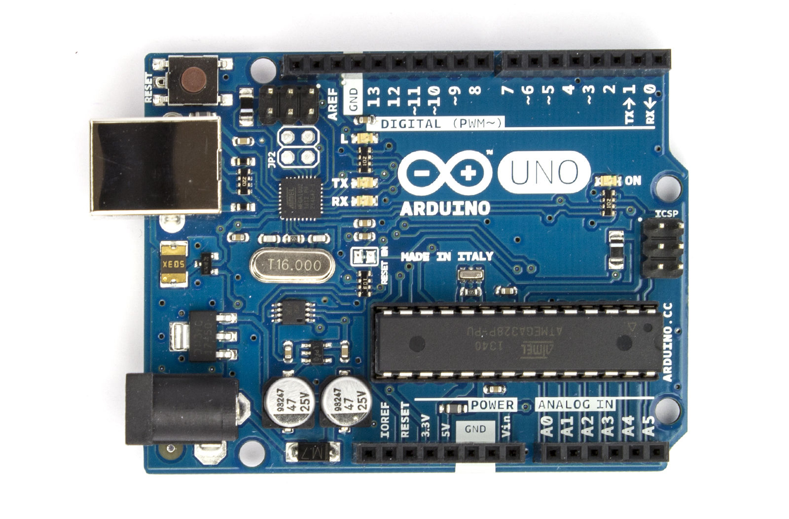
My Arduino configuration. 

In this image, you see a breadboard with an ultrasonic sensor, the Motor Shield atop the Arduino, a 9V battery powering the Arduino, and a 12V 8-AA battery pack powering the Motor Shield, which powers the electric motor. Essentially, I can disconnect and detangle this setup from this RC car frame, and attach it to any other RC car, to make it self-driving.


Schematic drawing of Arduino and Motor shields
with sensor, motor, and batteries

In this drawing, you see more clearly that there are only a few wires to be connected, and most of those are moving power from one component to another. If the Motor Shield VIN were not severed, the Arduino could probably run off the 12V power supply to reduce complexity. But that leads to the possibility of the Arduino processor running out of power if the motor were drawing too much. As I said above, the 2-battery setup has advantages and disadvantages. Also, the 9V battery could be replaced with any USB charger, including a large USB battery pack I also own. 


If you have any ideas, suggestions, improvements, or criticisms, please comment.

Sunday, May 5, 2013

Sunday Update

Spark Core

Last week, Spark Devices launched the Spark Core on Kickstarter. This Arduino-powered, wifi-cloud-connected development device is designed exactly to make easier projects like mine. The Spark Core obviates my need to use Xbees, as the Core is exactly what I was trying to make, but better. I believe they beat me to it because their team has 4 members, while mine has just me.

The Kickstarter page shows a Twitter refrigerator magnet. My visualized refrigerator monitor would be pretty much that, but displaying temperature instead, with another wire running to the sensor placed within the refrigerator. It would also have an SD card inside, recording temperatures for long-term compliance or analysis.

LCD Screen

I assembled my LCD shield. Unfortunately it doesn't work. Soldering on breadbords is tricky and I'm not quite as skilled in EE as I like to believe. I didn't perform incoming QA on the LCD screen, so I don't know if the screen worked before I assembled it onto my LCD shield. Or it could have been a wiring mistake I made. Either way, I wanted to share some of the considerations I had when wiring it:

Atmel's ATMEGA168 only has 28 pins, of which only 13 are set up for digital output. Yes, you can modify the 5 analog input pins for digital output in software, but combining these 3 devices won't require that many.

Digital Pins

0
1
2
3
4
5
6
7
8
9
10
11
12
13


Wireless SD Shield: Working with this shield and the Xbee, I've come to understand that the shield uses SPI to allow the shield to work with both the wireless radio and the SD card without taking up 6 to 8 Arduino pins. Both the wireless radio and SD card use Arduino pins 11, 12, and 13 for communication. Pin 4 is used by the Arduino (the master device) to select the SD card as the subordinate device on the SPI bus, while pin 10 is used to signal that the wireless radio port is the subordinate with which the master device is communicating over the SPI bus (on pins 11, 12 and 13).


Digital Pins - Wireless SD Shield

0
1
2
3
4 SD select
5
6
7
8
9
10 Xbee Select
11 SPI MOSI
12 SPI MISO
13 SPI Clock


DHT11: Using this blog as my lab workbook means I don't have to relearn how a component works. This device won't even take up a digital pin -- its library automatically runs the single analog pin needed by the sensor.

LCD Shield: Controlling an HD44870 requires 6 pins - 1 for RS (Register Select), 1 for Enable, and 4 for data. The Arduino LiquidCrystal tutorial uses pins 2, 3, 4 & 5 for data, 11 for Enable, and 12 for RS.


Digital Pins - LCD Shield

0
1
2 D7 - LCD pin 14
3 D6 - LCD pin 13
4 D5 - LCD pin 12
5 D4 - LCD pin 11
6
7
8
9
10
11 Enable - LCD pin 6
12 RS - LCD pin 4
13


This presents a problem, as we're already using pins 4, 11 & 12 for the Wireless SD Shield.


Digital Pins - LCD Shield & Wireless SD Shield
0
1
2 D7 - LCD pin 14
3 D6 - LCD pin 13
4 D5 - LCD pin 12 & SD select
5 D4 - LCD pin 11
6
7
8
9
10 Xbee Select
11 SPI MOSI & Enable - LCD pin 6
12 SPI MISO & RS - LCD pin 4
13 SPI Clock


So I relocated the LCD pins to 2 & 3 for Enable & RS and 5, 6, 8 & 9 for data.

Digital Pins - revised LCD Shield & Wireless SD Shield
0
1
2 LCD Shield - RS - LCD4
3 LCD Shield - Enable - LCD6
4 SD Shield - SD select
5 LCD Shield - D4 - LCD11
6 LCD Shield - D5 - LCD12
7
8 LCD Shield - D6 - LCD13
9 LCD Shield - D7 - LCD14
10 SD Shield - Xbee Select
11 SD Shield - MOSI
12 SD Shield - MISO
13 SD Shield - Clock


Wednesday, May 1, 2013

Hardware Startups

Chris Dixon makes some great points in this post about the changing landscape of starting a company that sells electronics devices.


Slight Pivot

Wifi Website Controls for Arduino


One of my goals for this project was to have a website interface displaying temperature stats, available over wifi. I know this can be done, but I'm starting to think my Minimum Viable Product isn't Minimal enough. And, like others have said, a lot of people would like a simple LCD display showing their refrigerator's current temperature. So, I'm going to move the Wifi-website part of this project aside, and put in an LCD screen.

That said, the entire device is now made of pieces with which I've worked previously: Arduino Uno, SD card on Wireless SD shield, clone of HD44870 lcd display & DHT11 temperature sensor. Since I previously burned out my HD44870, I'll be assembling another one. This time, I've decided to attach the HD44870 onto a blank Arduino shield. I will have the shield soldered together today, and might get code onto it!

---

Thanks, seancneal, for suggesting another address to try with my Sainsmart LCD screen. Honestly, I'd kinda forgotten about that screen. I'll try this address and post an update.

Monday, April 29, 2013

MSP TryFi Prep

Today, I'm going to begin merging 2 disparate devices. We're going to start "pre-marriage counseling" for a union between 2 devices which can talk to each other, but aren't really intended to.

Bride and Groom


Our goal is to get the MSP-430 and the Xbee Wi-Fi radio to communicate. If we can have it report available networks over a serial connection, then it can host a webpage over wifi. To make this happen, we'll need to do several things:


1. Install CJBearman's XbeeWifi library into Energia
2. Make an SPI connection from the MSP to the Xbee -- 4 pins plus VCC (power) and ground
3. Make another connection for XbeeWifi library's 4 required pins
4. Transfer and run code


Sunday, April 28, 2013

Sunday Update

New Look!

I like orange!

New Inspiration

After re-reading CJBearmans documentation, I better understand the challenges with this project. I'm on the right track, as the library needs 3 more digital pins to better control the Xbee. (I wound up using Arduino Pin 5 for RESET, Pin 6 for ATN, and Pin 8 for DOUT.) Since the Xbee's designed to run at 3.3v and my Arduino Uno uses 5v, I believe I may have fried this Xbee radio.

Some drunken fool (possibly myself) scribbled out an idea on my whiteboard last night. I was eventually going to see if a TI MSP430 could handle both hosting a webpage and running an Xbee, but only after I got it all working on the Arduino. The MSP430 is a much smaller, cheaper development kit than the Arduino Uno, and its 3.3v processors run much slower -- 12MHz (or even 1Mhz) vs the 80Mhz processor in the Uno. But the processors cost about 1/10th as much as the Atmel processors inside the Arduino Uno, which is important for production. And someone has created Energia, an open-source copycat of the open-source Arduino compiler -- meaning we can literally run the same code on both processors. This means I can take all of the code with which I've been working on the Arduino and simply keep working in Energia (after importing CJBearmans XbeeWifi library into the other program)

So tomorrow I'll again be "Frankensteining" together 2 devices that aren't designed to work together. Isn't development fun?!?

Kickstarter

One main goal of this project has been to crowdfund with Kickstarter to start a (small or large) company.  I will have more information about this part of the project later this week.

GilgaTech

I've always planned for this page to be a workshop notebook, mainly focused on this company I'm learning to build. I've decided to launch Gilgamech's Technologies for my more general-purpose technology thoughts and pursuits.

Wednesday, April 24, 2013

TryFi 4

TryFi 4 - The SPI Try

I've been trying to line up which pins to provide the XbeeWifi library, so it can communicate with the Xbee wifi radio. Once I have this completed, it should be somewhat easier to make it host a webpage over the wifi connection.

Let's go over what I have learned so far:
*SPI uses 5 pins to communicate:
  -MOSI = Master device (Output) to the Subordinate device (Input)

  -MISO = Master device (Input) from the Subordinate device (Output). Named after a tasty soup, this is opposite of MOSI.
  -CLK = Clock. It's a circuit in a processor that's like a camshaft in an engine, in that it synchronizes all of the other parts. One master device can provide the clock signal to multiple subordinate devices.
  -ATN =Attention This allows a subordinate device to tell the master device that it has information to send. 
  -SEL = Select. This pin is used by the master device to tell a subordinate device to transmit data. This allows designs where MOSI, MISO, and CLK are shared between several subordinate devices, and each subordinate will only use the MOSI and MISO lines (also known as a Bus) when their SEL is turned on during the CLK pulse. This would save pins, allowing more subordinates per master. 

*CJBearman's XbeeWifi library calls for 3 of these plus 1 additional pin:
  -RESET - Reset. This is optional, but allows for the Xbee to be reset into SPI mode by the library. The other option is to manually configure the Xbee with X-CTU.

*The Xbee uses the following pinouts:

  -MOSI = 11

  -MISO = 4

  -CLK = 18

  -ATN = 13

  -SEL = 17
  -RESET = 5

*Arduino Uno SPI pinouts:
  -MOSI = 11 & ICSP 4

  -MISO = 12 & ICSP 1

  -CLK = SCK = 13 & ICSP 3

  -ATN = 

  -SEL = 10 (SS)
  -RESET = 1 & ICSP 5

Something to note here is the Arduino Uno's ICSP header has these same pins -- it seems pin 11 and ICSP 4 both connect to the same pin on the Atmel ATMega328. A good post with some very technical details helps me to sort this out. I'm not completely sure that Reset on the Uno is the same Reset as the Xbee is looking for. 

So far, we have:
Select: 10
Atn: ? 
Reset: 1?
DOUT: 12

For the library to work, we have to have at least the first 2 filled in. Out of desperation, I'm manually wiring the Reset and ATN pins to 5 and 6

Here the yellow wire runs from Arduino
Pin 5 to Xbee pin 5, while the white wire
runs from Arduino Pin 6 to Xbee Pin 17 

Looking at the pinouts...

Monday, April 22, 2013

TryFi 3

In the past post, I did the easy work of getting the XbeeWifi code running on the Arduino. This time, I'm looking at pinouts to connect the Xbee into a Wifi program. This is the last major puzzle piece I haven't yet had.

Tryfi 3 - Try and try again

More specifically, I'm trying to fill in these 4 variables with the numbers of the correct pins:  

  bool result = xbee.init(XBEE_SELECT, XBEE_ATN, XBEE_RESET, XBEE_DOUT);

Higher in the code, we see the actual pinout values in use:

  #define XBEE_RESET 20

  #define XBEE_ATN 2
  #define XBEE_SELECT SS
  #define XBEE_DOUT 23

After re-reading the Xbee Spec and the Introduction to SPI on Xbee, I have some slightly clearer understanding of SPI as a hardware protocol, a way for 2 processors to communicate. Basically, we're setting the right pins so the Xbee's processor and the Arduino's processor can hear each other. 

From the Xbee Spec, we can see the pins on the Xbee that we're looking for -- Reset = 5, ATN looks like ATTN = 13 (ignore the n), and Select could be SSEL = 17. DOUT looks like 2, but I'll come back to that later.

Well, I'm getting lots of info on what pins the Xbee uses, and lots of this SPI stuff is supposed to be universal -- basically a small but fairly complex universal language which all processors can speak. It's like UART, (universal asynchronous receive & transmit) which is basically a much simpler language that all processors can speak. There are lots of these "universal" languages, but SPI is the one we're interested in.

Here is one of the diagrams from 
the Xbee Spec. Note the highlight.

Something to note is 2 different naming methods for the connections -- DIN & DOUT vs MOSI & MISO. 'Master Out Slave In' matching to 'Data In' -- since the Xbee will be 'slaved' to the Arduino's clock frequency, the way ancient sea slaves rowed to the drummer's beat. 'Master In Slave Out' connections are also named the Data Out connections from the Xbee. So one of the 4 variables we're looking to fill is the Xbee DOUT, which is also the SPI MISO connection (which is actually pin 4 on the Xbee, not pin 2 -- pin 2 is the UART DOUT).

Maybe I'm looking at this the wrong way -- I have lots of info about how Xbee uses SPI, but what I need to is the pins the *Arduino* uses. Well, Google directs us to a gold mine! Aha! Looking down the page, we finally get our answers:


So this gives us 1 of the variables, and confirms another -- We know that Xbee DOUT should change from 23 to 12, and we know Xbee Select is correct in being set to SS, as SS is a variable for 10. Now, we just need the Xbee Atn and Xbee Reset pins.


Friday, April 19, 2013

TryFi 2

TryFi 2 - The Second Try


This morning, I'm hacking on the XbeeWifi again.
I'm still looking for a good solution to prevent static 
shock. The Arduino retail box works pretty well.

Looking over cjbearman's github page, the technical details are fierce, but luckily examples are included. After loading several up, I'm starting to see common patterns in the code. There's a couple extra subroutines (modules? functions? O_o) to handle different wifi scanning features. Unlike the Ethernet shield and library, we'll have to manually scan and handle data coming in and out. This could get messy.

Well, let's give it a try. Network Scan sounds like a good example -- it should output a list of available wifi networks, which is almost always an essential feature.

XBee Init Failed? Loop forever - game over, man!

What happened here? Well, the Arduino sent signals over to the Xbee, but the Xbee didn't respond. Why not? Well, this is the (boolean: 1 or 0) result of  a process on the Arduino, sent across 4 pins from Arduino to Xbee. Looking at the code, we see this in the line:

   bool result = xbee.init(XBEE_SELECT, XBEE_ATN, XBEE_RESET, XBEE_DOUT);

What does this mean,, when translated from C to English? We're going to set Result to either 1 or 0, based on what xbee.init says about the 4 variables between the parentheses. If you want to be a programmer, please don't use all caps for your variable names. So where are these variables declared? At the top of the code: 

"You're supposed to change these variables to
match your board's connections, you noob!"

Yea, so I forgot to change my pinouts. I'm not even sure which Arduino Uno pins connect to the Xbee. So the Arduino is expecting to use pin 20 for the Xbee Reset feature, and 23 for DOUT....so let's change that. 

Xbee Pinouts

So where do we find the correct variables? First, let's start with the Xbee pinout:

This is the same 20-pin Xbee shield which can be seen
in this post's first image -- it's plugged into the Wireless
SD Shield.

We need 4 variables from the Xbee - Select, Atn, Reset, and the D-out. Right away we see pin 5 is Reset and pin 2 is Data Out, now we'll need to see how those get routed through the Wireless SD Shield and into the Arduino. Select and Atn aren't obvious from this, but maybe they'll pop up in the specifications. 

SPI


Looking at the scary schematic, the Arduino Wireless SD Shield page, and cjbearman's github, it's really not obvious which pin is actually used for which output. But his github does describe this library using SPI to communicate. Wireless SD Shield takes up pins 11, 12, & 13 for SPI, along with pin 4 for the SD card select. An Introduction to SPI on Xbee has a table which shows 5 pinouts, including the clock pinout. I'm not sure exactly how SPI works, but I feel like I'm close. 

Wrapup

I'm slightly satisfied with today's progress. Seeing the code produce a confirmed failure means we're almost certainly on the right track, and it's just a matter of finding the right pins. Once that is done, we can start connecting to networks, exchanging data, and hosting a webpage. 

Also, some serendipity - I've accidentally mixed a working Arduino with a damaged one recently, when they were in the same box, and now they both work. Maybe it was just a memory cell that had to discharge. Maybe it was hacker's luck. 


Thursday, April 18, 2013

Self-Driving Pivot


I'm planning a pivot to one of my ideas -- the Self-Driving Trash Can is being reimagined as a Gardening robot, driving through a patch of ground and either pulling weeds or deploying pesticide on them. How do they know a weed from a "good" plant? That's a very good question, and my answer is better.

What's a good word for plant which isn't a weed? Let me know in the comments!

Wednesday, April 17, 2013

TryFi

The Fridge Monitor Progresses

I have been working with the XbeeWifi  page, and hacking together a sketch. I expect to have this figured out by Friday, and will post updates as they arrive. So far, joining a WIFI network seems easy enough, and since this is all editable code, we can definitely configure routines to allow scanning and selecting of WIFI networks.

Looking at the Programming Arduino book I mentioned in a previous post, the ability to create and handle websites is very code-intensive, but allows websites hosted by Arduinos to have a very high level of control over the device -- able to turn pins on and off, which means controlling all kinds of lights, motors, sensors, and other devices is trivial from a basic webform -- imagine every device in your house hosting its own webpage, where you can turn it on and off, among other things.


Tuesday, March 19, 2013

Inactive

It's been more than 45 days since my last update. Sadly I haven't been making much progress on my projects during that time. I did have a few views from an HN comment, and with the valuable yet free advice from other hackers, I have a couple updates to my Fridge Monitor.

Saturday, February 2, 2013

Wireless temp sensor

In my last post, I talked about hooking up a DHT11 temperature sensor to your Arduino and monitoring it over the serial connection. This is one of the building blocks of the Fridge Sensor. Other puzzle pieces include the wifi connection, the webpage hosting code, and figuring out how to keep the battery from chilling out.


After creating libraries to get the DHT11 working, we could get output over a serial USB connection. The next step is to extend the serial connection over a wireless connection. Extending to wifi will come later, first we have to work with the Xbee connection.


Originally, when I bought my Xbee antennas, I thought they were designed to connect with wifi hotspots and networks. Nope. While they use the same frequency range as wifi, they actually use slightly different frequencies and channels. The plus side is they *just work* quite nicely. Additionally, they can be configured to work with just specific other Xbee antennas, based on addressing. Check out the Wireless Shield page fore more info.

After getting the serial test working in that blog post, I took 2 Arduinos and attached a Wireless Shield to each. Then I attached a wifi Xbee shield to each of them.


I attached one to my PC, and put the other in my fridge. Say hi to my pickles!


With the temperature monitoring program from the last post running on my fridge model, I was almost ready.  I uploaded the BareMinimum example sketch from the Arduino library to the Arduino attached to my PC, and switched the switch on the Wireless Shield to USB -- these allow the PC to directly interface with the Xbee. I don't know why, but I had to take off the Xbee to upload the example.

Once I got the USB connection to recognize the Arduino, simply clicking on the Terminal tab in X-CTU brought up the same humidity and temperature output as was reading over the serial monitor. The serial connection is happening literally over the wireless. This is cool.


It takes a little while for the sensor to cool off, but it was reading 2.0C reliably for a while. This image is from a later demonstration. As you can see, the temperature and humidity readings eventually trail off into a series of "Ready"s, which are the Arduino rebooting. It's running out of power. Magically, if you take it out of the fridge, it'll start working in about 5-15 minutes, as the battery warms up and can start generating electricity again.

---

As I was writing this, my 2nd Arduino, the PC model, has stopped working. It no longer shows in the Arduino IDE nor X-CTU, but still does in Device Manager. This is the 2nd Arduino I've broken, and it's putting a serious crimp in my development abilities. I suspect I'm causing small amounts of electrostatic shock to damage the internal circuits. Still frustrating.

Friday, January 25, 2013

DHT11 temperature sensors

=== This log post is in raw form. This is not the final presentation, but making information available is more important than making it pretty. ===

Today I received 4 DHT11 temperature sensors. They were a deal, but it turns out they're all labeled in Chinese.


Google searches bring us to the Adafruit page for the device. Under the downloads tab, you'll find the manual in Chinese. Fortunately, Google Translate gives us something passable. Even better, there's a similar guide in English linked from Adafruit.


The guide lists various specifications for accuracy and operational speed. It mentions a 1 second delay several times. Near the bottom is the pinout. While the device has 4 pins, only 3 of them are used; one is merely there to physically connect the device to the mounting board. This is good because those pins are thin and flimsy. I bent one putting it into the solderless board.

Pin Name
Note
1
VDD
Powered 3-5.5VDC
2
DATA
Serial data, single-bus
3
NC
Empty feet vacant
4
GND
Ground, power supply negative

But this is backwards, if you look at the label. From the above image, the VDD goes on the rightmost pin, GND on the left, with the DATA next to the VDD. The code sample that worked for me specifies the DATA pin should connect to the Android's analog A0 pin.

Elsewhere the guide mentions a single-pin bus, so I'm assuming it works much the same as the Ping ultrasonic distance sensor, using the same pin as input and output.

So how to get it working on the Arduino? 

First, you need to make a DHT11 library. You'll need to make a new folder in your /arduino/libraries/ folder. Then you'll need to fill it with dht11.h and dht11.cpp, which tells the Arduno's C++ compiler how to handle the commands for the DHT11. I got the files from the bottom of this page -- you actually make a text file, rename it, then copy the code from the page, and paste it in the renamed text file. (You might be able to click "get code" at the bottom of each section, but all that did for me was display the code in my browser).

Once you've got the libraries in place and have restarted the Arduino IDE, you should be ready for code. While the code for the libraries seems to work great, the example code on the same page provided a repeating pattern of letters and numbers and weird shapes. Through some digging, I was able to find another source. The first section of code on this page, however, provided a nice, repeating output:


Current humdity = 38.0%  temperature = 21.0C


So I think we have a keeper. I'm planning on combining this with the xbee wifi device, to make a networked wireless device you put in your fridge. I want it to host a webpage, showing temperature statistics for your refrigerator. I know it's not a moving robot, but robots are about automation. Maybe I can kickstarter this!


Xbee

=== This log post is in raw form. This is not the final presentation, but making information available is more important than making it pretty. ===

Today in the mail I got a couple Xbee wifi modules. They fit on the Wireless SD shield, among others. When I was buying them, I thought Xbees would just connect to wifi hotspots, or at least enable an Arduino to do so. This isn't exactly the case. As I described in the Wireless temp sensor post, they use the same frequency range as wifi, they actually use slightly different frequencies and channels. This does mean that the modules communicate with each other right away out of the box -- that is, they just work. And they can be programmed to be more selective about which Xbee antennas they connect with, based on an addressing system. Check out the Wireless Shield page fore more info.

Physical pixel is a Communications Example, and while I didn't get the pixel image going, I was able to have the LED activate when pressing H and deactivate when pressing L in the X-CTU terminal. 

Wifi

One of my big goals in working with these devices is being able to control wifi capabilities. I don't just want to have devices scan for networks and host webpages on them, I want them to be able to pinpoint wifi devices and travel to the device -- which would sometimes be a device held by a human, and sometimes be a charging station, device needing service, or some other target. I don't know how much of that can be done by an Arduino -- the ATMega processor isn't that beefy, so I might need to move up to an ARM, which means moving into Linux and much more developed networking stacks. It would be a solved problem from that perspective, and the weight and power differences aren't too big...

Like with the DHT11 temperature sensor, we'll need to add a couple of libraries to the Arduino IDE: XbeeWifi.cpp and XbeeWifi.h. Both can be found on this page, along with some examples for how to use it in code. You'll have to goto your Arduino/Libraries folder and make the /XbeeWifi folder, then copy the text for those files and save them in the /XbeeWifi folder.

Restart Arduino, and the libraries should be good to go. 

I'm still working on this part of the project. Check back later for more info!

Wednesday, January 9, 2013

OpenCV

OpenCV, or Open Computer Vision, is an open-source project to open up computer vision to the masses. Computer Vision is a process where a computer receives images from a camera somewhere, interprets these as an array or matrix, and does some math to analyze them. Sometimes the math is simple, like "find the orange circle, and the green circle, then line them up." Sometimes it's more difficult

Suddenly I realize we can make red and green circles on the walls with LEDs. Can we make "different colors" of infrared light with LEDs? Is anyone making infrared CCDs yet?


Sainsmart LCD2004

This winter, a gift I received was the Sainsmart LCD2004, which is a 4-row, 20-letter wide display, also known as a 20x4.


I'm happy to have received it, as I just bricked a 16x2 (2 rows, 16 letters wide) in early December. Interestingly, both use the same controller, Hitachi HD44780, to store and push the actual outputs to the screen. 


My LCD2004 has the PCF8574AT controller made by NXP, an 8-bit I/O converter for the 2-wire I2C bus. The PCF8574AT listens to the Arduino quickly on 2 lines, then spreads that info across 6 lines for the HD44780. This means the display will only take 2 pins instead of 6, and these aren't even commonly-used pins -- all 13 of the pins I like to use are still available. A dial potentiometer, to dim the display, is built in. A data sheet is available.


With the 16x2, I had to control all of the signals manually. This took up 6 of the Arduino's 13 pins, and a significant amount of code. But there's no reason to have to do this by hand when we have libraries and microcontrollers to handle it for us. How do microcontrollers talk to each other? Phillips developed a protocol, a common way of signalling, called Integrated Internal Communication or I2C.

Getting new devices means learning how to configure them, which is a big sticking point for this model of display. This blog post says to use the Arduino's A4 and A5 ports for SDA and SCL instead of the board's SDA and SCL ports, which are next to AREF and GND. The Arduino website confirms this: Uno, Ethernet [use] A4 (SDA), A5 (SCL). This forum post discusses which address to use in the code. Several of the recommended addresses, such as 0x27, 0x20, and 0x30 aren't working.


SCL is the Clock line, and SDA is the Data line. The Atmel ATMega chip doing the processing inside an Arduino runs at 16 megahertz, which is another way of saying it has a clock circuit sending 6 billion on/off signals per second. Hertz is an old-fashioned way of saying "cycles per second", and Mega relates to billions of something. So the SCL could be 16 MHz, but will probably be a much slower 100 million times per second (100 kHz or 0.1 MHz). 

Whenever the Clock line pulses, the value (1 or 0) on the Data line is written into that spot in memory --which is to say the magnetic charge (HIGH or LOW) for the patch of copper which creates that spot of memory is changed to match the Data line's magnetic charge. This happens once per clock cycle. The location written to usually changes on the clock cycle, and in this way information can be transposed from a series of inputs across 1 wire into multiple parallel inputs with their own wires.

None of which tells me which address to use. The author of the new LCD library says The base address for the PCF8574 is 0x20 and the base address for the PCF8574A is 0x38. Unfortunately, the base address my PCF8574AT isn't specified. I suppose I'll have to try every address, or grab a multimeter and test every pinout at every address, like I have that kind of time. But seriously, I'm not even sure the defined pinouts are correct.

Next steps:
A very thorough primer on I2C.
I2C Sniffer.
Sample code which is supposed to work, but doesn't.