This winter, a gift I received was the Sainsmart LCD2004, which is a 4-row, 20-letter wide display, also known as a 20x4.

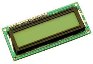
My LCD2004 has the PCF8574AT controller made by NXP, an 8-bit I/O converter for the 2-wire I2C bus. The PCF8574AT listens to the Arduino quickly on 2 lines, then spreads that info across 6 lines for the HD44780. This means the display will only take 2 pins instead of 6, and these aren't even commonly-used pins -- all 13 of the pins I like to use are still available. A dial potentiometer, to dim the display, is built in. A data sheet is available.

With the 16x2, I had to control all of the signals manually. This took up 6 of the Arduino's 13 pins, and a significant amount of code. But there's no reason to have to do this by hand when we have libraries and microcontrollers to handle it for us. How do microcontrollers talk to each other? Phillips developed a protocol, a common way of signalling, called Integrated Internal Communication or I2C.
Getting new devices means learning how to configure them, which is a big sticking point for this model of display. This blog post says to use the Arduino's A4 and A5 ports for SDA and SCL instead of the board's SDA and SCL ports, which are next to AREF and GND. The Arduino website confirms this: Uno, Ethernet [use] A4 (SDA), A5 (SCL). This forum post discusses which address to use in the code. Several of the recommended addresses, such as 0x27, 0x20, and 0x30 aren't working.
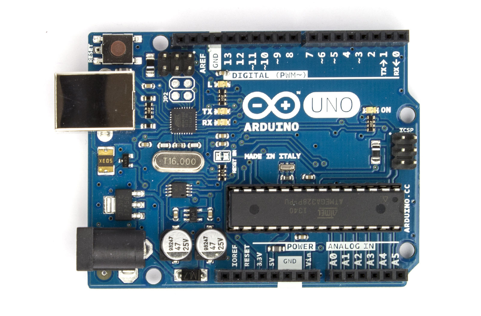
SCL is the Clock line, and SDA is the Data line. The Atmel ATMega chip doing the processing inside an Arduino runs at 16 megahertz, which is another way of saying it has a clock circuit sending 6 billion on/off signals per second. Hertz is an old-fashioned way of saying "cycles per second", and Mega relates to billions of something. So the SCL could be 16 MHz, but will probably be a much slower 100 million times per second (100 kHz or 0.1 MHz).
Whenever the Clock line pulses, the value (1 or 0) on the Data line is written into that spot in memory --which is to say the magnetic charge (HIGH or LOW) for the patch of copper which creates that spot of memory is changed to match the Data line's magnetic charge. This happens once per clock cycle. The location written to usually changes on the clock cycle, and in this way information can be transposed from a series of inputs across 1 wire into multiple parallel inputs with their own wires.
None of which tells me which address to use. The author of the new LCD library says The base address for the PCF8574 is 0x20 and the base address for the PCF8574A is 0x38. Unfortunately, the base address my PCF8574AT isn't specified. I suppose I'll have to try every address, or grab a multimeter and test every pinout at every address, like I have that kind of time. But seriously, I'm not even sure the defined pinouts are correct.
Next steps:
A very thorough primer on I2C.
I2C Sniffer.
Sample code which is supposed to work, but doesn't.
I'm sure you figured it out by now, but:
ReplyDelete#define I2C_ADDR 0x3F
Thanks, I'll try that.
Delete